7、URDF Model
7、URDF Model7.1、Overview7.2、Links(1)、Introduction(2)、Sample code(3)、Label introduction7.3、Joints(1)、Introduction(2)、Sample code(3)、Label introduction7.4、launch file introduction7.5、URDF Visualization
Function pack path:~/software/transbot_library/src/transbot_description
7.1、Overview
URDF is Unified Robot Description Format.
x <robot name="transbot_description">
</robot>The first line is required for xml, which describes the version information of xml.
The second line describes the name of the current robot; all information about the current robot is contained in the [robot] tag.
URDF mainly includes two parts: Links and Joints, with the suffix .urdf.
Links: Links, coordinate systems and geometric relations.
Joints: The connection relationship between joints and Links.
7.2、Links
(1)、Introduction
In the URDF descriptive language, link is used to describe physical characteristics.
- Describe the visual display, the
<visual>tag. - Describe collision properties,
<collision>tag. - Describe physical inertia,
<inertial>tag is not commonly used.
Links can also describe link size (size) \ color (shape) \ inertial matrix (inertial matrix) \ collision properties (collision properties), etc., each Link will become a coordinate system.
(2)、Sample code
xxxxxxxxxx <link name="base_link"> <inertial> <origin xyz="-0.011 0.0002 -0.00832" rpy="0 0 0"/> <mass value="1.1011218463245"/> <inertia ixx="0.00683403160871643" ixy="-1.43326126624159E-06" ixz="0.000665507738691208" iyy="0.0091844048006001" iyz="3.7191085325542E-06" izz="0.0114582299070878"/> </inertial> <visual> <origin xyz="0 0 0" rpy="0 0 -1.5708"/> <geometry> <mesh filename="package://transbot_description/meshes/base_link.STL"/> </geometry> <material name=""> <color rgba="0 0.7 0 1"/> </material> </visual> <collision> <origin xyz="0 0 0" rpy="0 0 -1.5708"/> <geometry> <mesh filename="package://transbot_description/meshes/base_link.STL"/> </geometry> </collision> </link>The name attribute in the <link> tag is required, which describes the name of the current link and is unique.
(3)、Label introduction
【origin】The tag describes the pose information; the xyz attribute describes the coordinate position in the large environment, and the rpy attribute describes its own posture.
【material】The tag describes the pose information; the xyz attribute describes the coordinate position in the large environment, and the rpy attribute describes its own posture.
【geometry】The tag describes the shape; the main function of the mesh attribute is to load the texture file, the file address of the filename attribute texture path.
【geometry】The label also includes other label descriptions:
xxxxxxxxxx<box size="1 2 3"/><cylinder length="1.6" radius="0.5"/><sphere radius="1"/>
7.3、Joints
(1)、Introduction
Describe the relationship between the two joints, motion position and speed limits, kinematics and dynamics properties.
Joint type:
fixed: Fixed joints. Movement is not allowed, it plays a role in connection.
continuous: Rotating joints. Can continue to rotate, there is no limit to the angle of rotation.
revolute: Rotating joints. Similar to continuous, there is a limit to the rotation angle.
prismatic: Sliding joints. Move along a certain axis, there are position restrictions.
floating: Floating joints. With six degrees of freedom, 3T3R.
planar: Planar joints. Allow translation or rotation above the plane orthogonal.
(2)、Sample code
xxxxxxxxxx <joint name="astra_joint" type="revolute"> <origin xyz="0.0484 0 0.10494" rpy="0 0 0"/> <parent link="base_link"/> <child link="astra_link"/> <axis xyz="0 0 1"/> <limit lower="-0.52358" upper="0.52358" effort="100" velocity="1"/> </joint>The name attribute in the 【joint】 tag is required, which describes the name of the joint and is unique.
Fill in the six joint types corresponding to the type attribute in the 【joint】tab.
(3)、Label introduction
【parent】和【child】子标签代表的是两个要连接的【link】,和【link】中的name属性对应;在此处将【parent】作为参照物,【child】围绕【parent】进行旋转。
【origin】:子标签,指的是旋转关节于parent所在坐标系的相对位置。
【axis】:子标签表示【child】对应的【link】围绕哪一个轴旋转。
【limit】:子标签主要是限制【child】的。
【mimic】:描述该关节与已有关节的关系;
【safety_controller】:描述安全控制器参数。保护机器人关节的运动。
【parent】 and 【child】 subtags represent two [link] to be connected, corresponding to the name attribute in [link]; [parent] is used as a reference, and 【child】 surrounds 【parent】 to rotate.
【origin】: It is a subtag, which refers to the relative position of the revolute joint in the coordinate system where the parent is located.
【axis】: It is a child label, which indicates which axis the corresponding [link] of [child] rotates around.
【limit】: It is a child tag, mainly used to limit [child].
【mimic】: Describe the relationship between the joint and the existing joint;
【safety_controller】: Describe the safety controller parameters. Protect the movement of robot joints.
7.4、launch file introduction
The launch file is an xml file used to describe the startup of a node, and it can can start multiple nodes at the same time.
Sample code
xxxxxxxxxx<launch> <arg name="use_gui" default="false"/> <param name="robot_description" command="$(find xacro)/xacro '$(find transbot_description)/urdf/transbot_astra.urdf'"/> <group if="$(arg use_gui)"> <node name="joint_state_publisher" pkg="joint_state_publisher_gui" type="joint_state_publisher_gui"/> </group> <group unless="$(arg use_gui)"> <node name="joint_state_publisher" pkg="joint_state_publisher" type="joint_state_publisher"/> </group> <node name="robot_state_publisher" pkg="robot_state_publisher" type="robot_state_publisher"/> <node name="rviz" pkg="rviz" type="rviz" args="-d $(find transbot_description)/rviz/transbot.rviz"/></launch>The name of the package to be started with the pkg attribute, the name of the type executable file, and the name of the node after the name executable file is started.
【param】The sub-tag is the result output after xacro executes xxx.urdf as the value assigned to robot_description.
【arg】 subtag, the name attribute is the parameter name, and the default attribute is the default parameter.
7.5、URDF Visualization
Open the command line and execute the following commands in sequence.
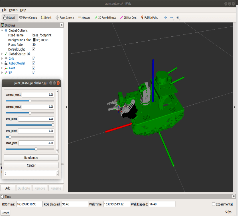
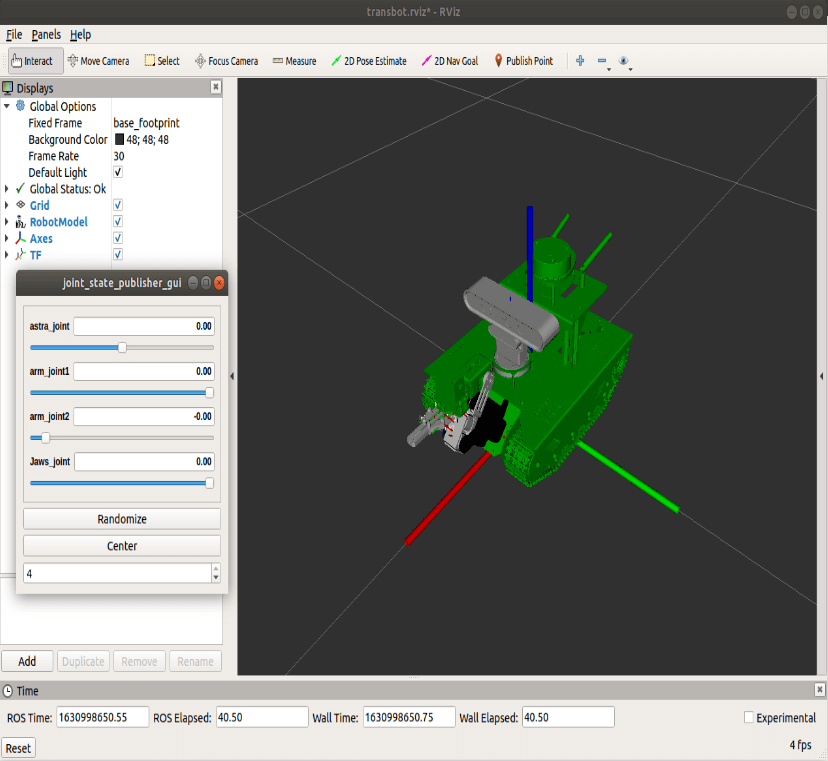
xxxxxxxxxxroslaunch transbot_description display_astra.launch # Astra cameraroslaunch transbot_description display_camera.launch # Ordinary camera- Sample picture
The red axis is X axis; the green axis is Y axis; the blue axis is Z axis; the coordinate system composed of three axes is called the base coordinate system.
Adjust the [joint_state_publisher_gui] component to rotate the servo.